Binary numbers and Voltage Levels
Binary digits are 0 and 1. In digital logic these two digits are use to represent two voltage levels.
Signals in digital electronics have two distinct voltage levels with built-in tolerances for variations in the voltage
A valid digital signal should be within either of the two shaded areas

AND gate
Boolean Expression
X = A . B
Logic Diagram Symbol

Truth Table

OR gate
Boolean Expression
X = A + B
Logic Diagram Symbol

Truth Table

Tri-state buffer
Inverter
Boolean Expression
X = A'
Logic Diagram Symbol

Truth Table

XOR gate
Boolean Expression

Logic Diagram Symbol

Truth Table

NAND Gate
Boolean Expression
X = (A . B)'
Logic Diagram Symbol

Truth Table

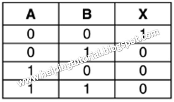
NOR gate
Boolean Expression
X = (A + B)'
Logic Diagram Symbol

Truth Table
No comments:
Post a Comment